|
|||||||||||||||||
Since the age of 10, now some 39 years ago, I have always dreamt of building robots. Back in those days all I had was lollipop sticks and old radio bits. I would glue and bolt bits together in the hope that somehow, like a Disney Movie, I could magically spark life into my creation. These days the technology has caught up with the dream in what can only be described as a fantastic and maybe terrifying way, a watershed moment has been reached and technology unlike anything seen before is now available to the potential builder
|
|||||||||||||||||
Modern chips have become very much “PLUG AND PLAY” to coin a phrase. When you go on to most electronic suppliers sites there are many ready to go solutions available for the modern D&T teacher. So why don’t we all embrace them? Well I can honestly say that because electricity is invisible and at first it seems to do many things that don’t make any sense, unlike resistant materials it isn't visible why something doesn't work, what’s more if you are bamboozled by it all solving a problem can be near impossible. In reality 90% of all electronic problems are down to bad soldering, or misreading how components are used. So how do we take out the soldering element? Prototype boards or breadboards as they were nicknamed have been around for many years but they used on their own present as many problems as solutions, particularly as the circuit becomes more complicated. So I propose a halfway house and towards that have designed a complete working Robot project with a whole series of sensors and programming solutions all available as an off the shelf ready to go solution from a website for both the beginner and the enthusiast. But before I get ahead of myself let me explain the philosophy behind the Robot and this project. I will be pitching at two main levels, beginner with little or no electronic experience, for them a ready made starter pack solution is available, for the hardcore electronics teacher everything is open source with etch masks and drill files so you can source the bits at cost. |
|||||||||||||||||
The BERT (Basic Electromechanical Robotic Trainer) teaching philosophy:- Many robotics experts agree that instead of trying to make robots that see, talk and walk we need to take a step back to understand how the brain works, how it senses its environment, how it solves problems presented to it. When you consider an ant can perform a number of very complex actions with a few thousand brain cells, that’s like your phone being smart enough to see, walk, navigate, communicate, forage for food, build massive constructions and reproduce, I suppose one out of seven isn't bad. Nature has 6 millions years experience in construction and systems redundancy, if one tiny transistor in any of the phones chips fail, the whole phone dies, if an ant looses part of a leg it will soldier on and compensate.
|
|||||||||||||||||
A quick technical bit for the harder core teachers. BERT will be based around the new Picaxe 28X1 microcontroller. The Picaxe series of chips are designed to be programmed in circuit without the need for an expensive programming unit, loosing the associated problems of breaking legs off the chips whilst constantly transporting them between your robot and the programmer. They can be programmed using a flowchart system inside Crocodile Technology or Picaxe BASIC and the Picaxe editor software is free to download from the Rev ED. The program download cable connects directly to most windows based PC’s. The 28X1 has twenty control pins and can control motors, servos and any wealth of electrical components, including analogue to digital inputs which can be used to measure variable sensors like light detectors, thermistors or variable resistors etc. The same paragraph for the beginner. Our robot will be based around a single chip brain because it is cheap, and has enough power to keep you busy and learning for months if not years, to quantify brain could easily run a full walking robot, its not the best available but it is a very good middle road option with lots of learning potential. The main brain has been kept as simple as is possible to keep assembly time down yet expansion options at their maximum. It may seem daunting to the beginners amongst us but that’s why ready built options are available. If you are new to electronics then it would make sense starting here, although the units are ready built the learning possibilities and expansion choices are still almost unlimited. Finally the BERT brain can be transplanted into any number of future projects from wheeled robots, to robot arms or animatronics so the room for long term expansion and additional learning is built in on day one. |
|||||||||||||||||
Building the brain. (For the hardcore user). The BERT robot Trainer can be built from the plans here .
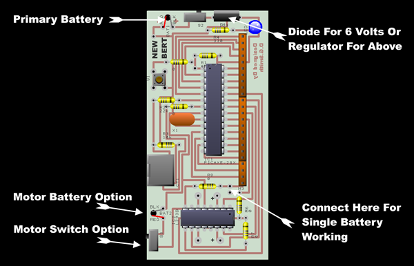
BERT’s component layout. The board can be run in a number of power configurations this is to allow the maximum level of choice when building the robot with regard to motors and will be essential when controlling servos which like 7.2volts at a later date. If the whole system including the motors is to be run at 5 to 6 volts then the component ALT1 next to the power switch can be a simple diode to complete the circuit and also protect against incorrect battery connection, to get this power to the motor chip the marked connection (Yellow Dotted Line) must be included this attaches the single power source to the motor chip without it no power would get to the wheels.
The dual voltage system circuit changes with an LS7805 regulator in ALT1 to control the 9 volt primary battery regulating it to 5v for use by the brain. The 12v secondary battery for the motors only, needs to be separated from the brain, this is done by leaving the yellow connection out, this would safely run the Picaxe at 5volts whilst allowing 12volt motors to be attached to the four motor connections. It is vital that the marked connection (Yellow Dotted Line) is not used in a twin power source configuration this keeps the primary battery and 12v apart if you put this connector in the 12v battery will fry your Picaxe even with the slider switch off, so be careful.
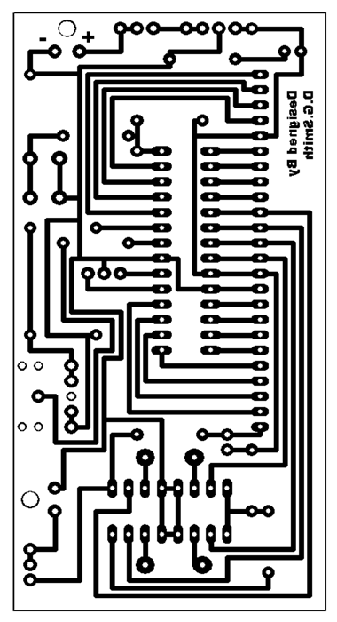
The artwork for the PCB For those who wish to etch their own it is also available for download
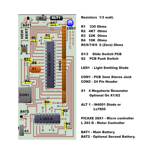
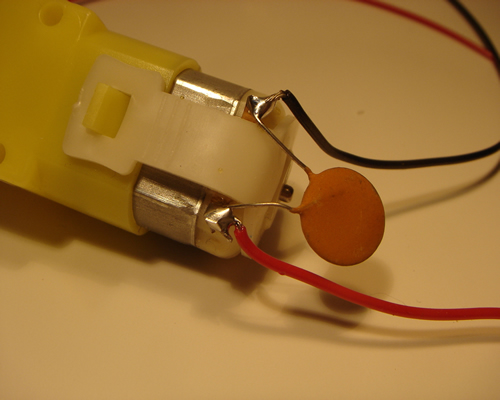
The parts list for our expert builders. They can be sourced from Rev Ed, Rapid and Middlesex University Teaching Resources. The hardcore users will now be knee deep in wires and chemicals, for the less experienced here are a few build tips. So lets move on to the other components. First the chassis, if you don’t wish to buy the ready made chassis any light piece of material will function, triple corrugated card, corrugated plasticard, 6mm or ¼” MDF, 3mm or 1/8” plywood, 3mm acrylic sheet, the size and weight being governed by the power of the motors you are intending to use. For most small motors a piece 6 inches wide by 8 inches long will suffice. Motors can come from any number of sources, the prototypes used low cost 120:1 geared motors from Middlesex University Teaching Resources who also supply the 75mm nylon wheels. Anything between 100:1 and 120:1 gearing should do, don’t be frightened of motors try different ones in this size category most motors these days will do the job, but remember if you exceed 5 volts you will need to build the dual voltage option into the motherboard. Attach wires to each motor and a de-coupling capacitor which is a must a 22uf (22 Microfarad) capacitor (Non polarised) will cope with most motors.
How the wires are added with the capacitor bridging between. If you leave out the bridging capacitor the microcontroller chip will keep freezing. Many robot projects whether they be Picaxe, Pic or Stamp based brains, stagnate at this point, for two reasons, motors are nasty electromechanical, magnetic field making lumps of magic and jiggery pokery and they do two things when you start them up they can swallow all the power and starve the brain and when you stop them they become mini generators and send power back to the brain the wrong way and poison it. So starting with the latter problem the bridging capacitor is like a little local overflow box when the motor switches off it deals with the spike that is made and if you experience problems start by doubling them up adding a second capacitor straight across the terminal side by side don’t daisy chain them. If the motor is using too much power then a second battery source must be put on the board and the yellow link cut. Program 1 should allow you to test the motors are working, if everything is working ok, the robot should sit there switching each motor on and off first forward then straight into reverse, this should be enough to highlight any problems if they are going to occur. The motors are connected directly to the circuit board
they will be on brain outputs 0,1,2,3, (One Forward & One Reverse Pin for each motor.). If you want to test the motors at this point type program1 into the program editor (The program editor can be downloaded free from the Picaxe website www.picaxe.co.uk , you will also need a programming cable which goes from your computers RS232 port to a 3mm stereo jack, or but the usb cable depending on the ports you have on your computer, they are available from REV ED and other Picaxe distributors (Links On the Picaxe site) or plans are also on the teaching robotics site to make your own. Program 1: - Motor test program. Main: Once you have sent this program the motors will rotate and reverse for 2 seconds in each direction. Don’t worry if you are having problems understanding what the code does we will go into much more detail about programming later. Wheels come literally in all shapes and sizes, wheels between 2” and 3” diameter should get your robot moving, don’t go too big speed is not what we are here for, fast bots need to react quicker and as a rookie programmer this could prove frustrating, skills first, speed second. The biggest hurdle when buying wheels will be getting a good fit on the motor shaft, the Como drills 100:1 motors have a 4mm output shaft which mates well with meccano wheels, but don’t be frightened about being adventurous Middlesex University Teaching Resources sell plastic wheels which can be drilled out to fit your motor shaft. With plastic wheels it is a good rule of thumb to drill your hole 0.5mm smaller than the output shaft of your motor, this will give a good tight fit, if they are both metal then you may have to go for size for size and employ a locking device (Grub Screw or Pin) try to avoid superglue, it can be dangerous and often gums up the works in the motor. Plastic wheels driving grip can be enhanced by fitting a rubber band as a friction tyre to the outer rim. Once we have the basic unit assembled with wheels we need to add a jockey wheel to allow the unit to move without dragging the plastic chassis on the working surface. I have used all types of third point of contact solutions from metal buttons to small wheels, but by far the simplest solution with the lowest friction and good wear characteristics is the humble glass marble, stuck to the chassis with hot glue (Watch for burns). They also come in different diameters to enable you to get the chassis running flat, the chassis from teaching robotics is designed to run with 75mm MUTR wheels and one plain glass marble. In the next article we will discuss adding and programming many types of sensor to your basic robot chassis built here, we will add and program whiskers to detect walls / objects, sonar to allow the robot to see into the distance, line followers, heat and light sensors to allow the robot to react like a life form. Places to obtain bits. Revolution Education - Has a full world distributor list for all Picaxe related items. Rapid online – Electronic bits Middlesex University Teaching Resources – Motors and wheels.& Electronic bits www.teachingrobotics.com – additional teaching resources and ready made kits.
|
|||||||||||||||||