|
|||||||||||||||||||
The Weatherstation is the biggest project that we have undertaken so far and it hits STEM in every criterion. This project is designed to be taught by anyone to anyone. If you have no skills in electronics this project will enable you to build your skills pack. If you are teaching year 7 the project has been broken down into simple three component circuits. If you are teaching years 10 or 11 the project will extend into wireless com's, ICT programming and much more. The weather station is intended to be a training base for many other projects. It solves circuits for heat, light, pressure, humidity, rotational encoding, flip flop measurement, wireless comm's, clock interface and memory interface. The heat circuit is digital made from two components. The Light Circuit is made from two components and produces an analogue voltage proportional to the light level. The Humidity Circuit is made from two components and also produces an analogue voltage proportional to the humidity level. The Shaft Encoder Circuit used to measure the wind speed is made from a single component and produces a square wave voltage (On / Off) as each pair of magnets passes the detector. And on we go the intention is to empower both staff and students not veil the subject in mystery.
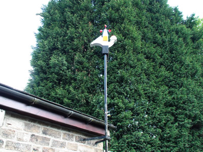
Long Term Test Installation
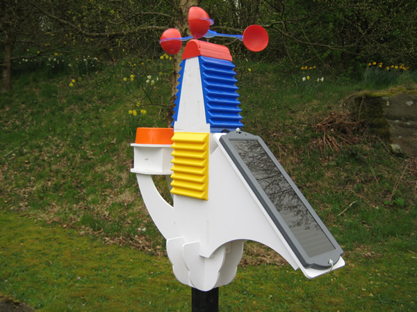
Our interest in weather seems to be hard written into our genes, for most of us the relevance to our daily lives is very thin often only altering the level of dress we choose. Unless you are an outside worker the weather will be no more than a minor discussion point whilst observed through a window from the comfort of a warm office or classroom. Despite this every news report world wide is followed with a weather report, regardless of how little it will affect 95% of the populations day. We invest fortunes in satellites and supercomputers running chaos theory all in a vain attempt to catch a jump on the short term future of our weather. This project will do nothing to reduce this "Obsessive" behaviour and will deal with the construction of an electronic school weather station that adds to the available data. I personally have always been interested in Meteorology and have two antique (non functioning) barometers that I have always promised to bring back into service. All our weather happens in the bottom layer of the atmosphere called the troposphere, which is six to ten miles thick. Meteorology is the study of the changes in temperature, air pressure, moisture, and wind direction in the troposphere. I spent some time looking at what other people had achieved on the internet and found many sites had interesting previous solutions some of which are present here plus my own ideas. Although all the basic circuits have been worked out and tested there is still scope for expansion and at the end we have suggested enhancement tasks students can undertake. The Weather Station uses a 28 pin Picaxe chip as the overall control the picaxe is the PIC of choice because of its in circuit programming ability. This removes the need to constantly transfer the chip over to a programmer and the danger of damaging the pins each time its transferred. The Station Measures :- Outdoor Ambient Light Level Outdoor Temperature Outdoor Humidity Wind Speed Air Pressure Rainfall Indoor Temperature Indoor Humidity
Data is transmitted wirelessly from the weather station to a base unit that passes the data to the computer and the logging software. Although this seems a very difficult project it has been laid out section by section to allow easy teaching/explanation of each of the control systems and each system is checked as it is installed to prove it works. As part of my research I invested in a proprietary weather station from Maplin, the information this provided has enabled me to confirm that the weather station here works correctly and it has given me a better understanding of how pressure effects weather. Maplin Weather Station
|
|||||||||||||||||||
This project presented a number of mechanical and electronic problems. When introducing the project to a class some of these elements would be worth the pupils thinking about. If we accept that measuring rainfall is one of the tasks the system should be able to undertake, how can we make it automatic? On traditional weather stations rain was captured in a container and the amount measured. This required a daily visit to the instrument at about the same time to measure and empty the container. The anemometer needs to measure the wind speed what alternative system could be used instead of the cups. E.G. Blades / Vertical S sheet like petrol station spinning signs. How will the circuit board be kept dry. What other systems could be used to power the system instead of a solar panel.
The Prototyping Stage1 .
Last Prototyping Stages.
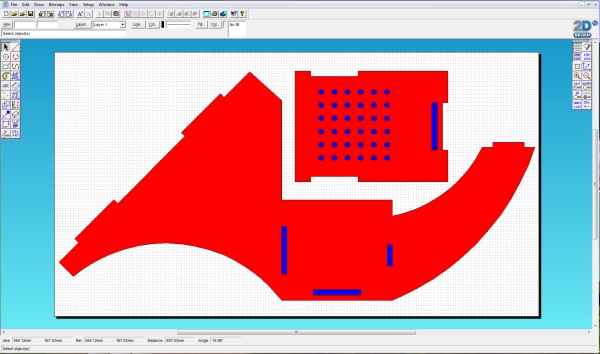
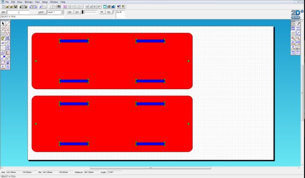
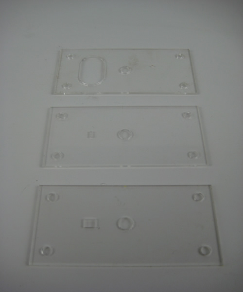
The Case :- These drawings are cut with a 3mm acrylic cutter on a Boxford A3 or equivalent with settings - Blue : Depth 6.5mm Inside - Red : Depth 6.5mm Outside - Green : Depth 6.5mm Drill The material is 6mm foamex glued with either pipe weld,UHU Glue or Tensol. Some schools have voiced difficulties in finding foamex. It is available from Barkston Plastic, Pontefract lane, Cross Green, Leeds. LS9 0DX. Tel. 0113 249 2222 Side A.
The array of holes are to allow air to circulate through the device for the humidity and temperature sensors. 2D Draw File - Download Mill Design File - Download
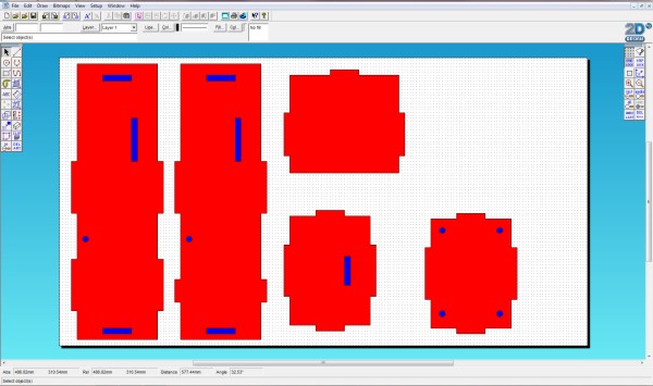
Side B.
The loose section is removed to expose the circuit board. 2D Draw File - Download Mill Design File - Download Connection Pieces.
The bottom has four holes to allow any water that ingress the system an exit. 2D Draw File - Download Mill Design File - Download Solar Panel Mount.
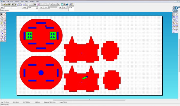
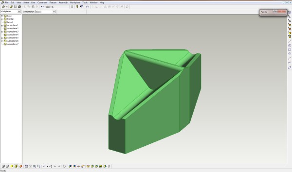
The green holes are used to take the radius out of the corner. 2D Draw File - Download Mill Design File - Download Rain Seasaw Container. These drawings are cut with a 3mm acrylic cutter with settings - Blue : Depth 6.5mm Inside - Red : Depth 6.5mm Outside - Green : Depth 2mm Drill - Magenta : 6.5mm Drill.
2D Draw File - Download Mill Design File - Download Anemometer Tower.
2D Draw File - Download Mill Design File - Download Sections Cut On The Laser Cutter
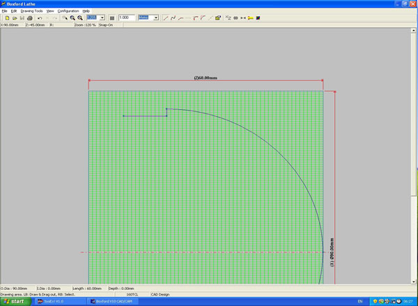
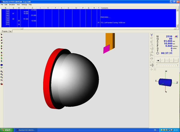
2D Draw File - Download 3D moulds for Vacuum Forming. Anemometer Cups Mould.
Lathe Simulation - Boxford Software
Lathe File - Download The rain gauge Seasaw.
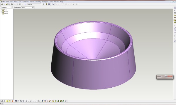
Pro Desktop File - Download STL File - Download The rain collector.
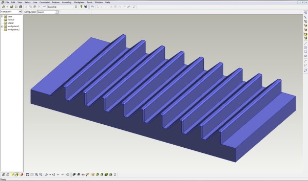
Pro Desktop File - Download STL File - Download Rain deflection louvre. Main Case Sides
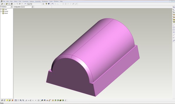
Pro Desktop File - Download STL File - Download Rain deflection for top of Anemometer Tower.
Pro Desktop File - Download STL File - Download Rain deflection louvre. Anemometer Tower
Pro Desktop File - Download STL File - Download
Assembling the Case Part 1
Assembling the Case Part 2
|
|||||||||||||||||||
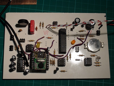
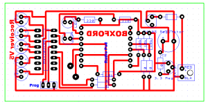
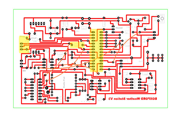
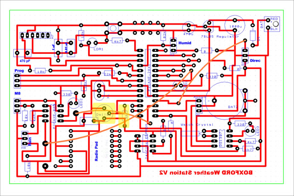
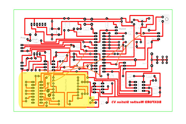
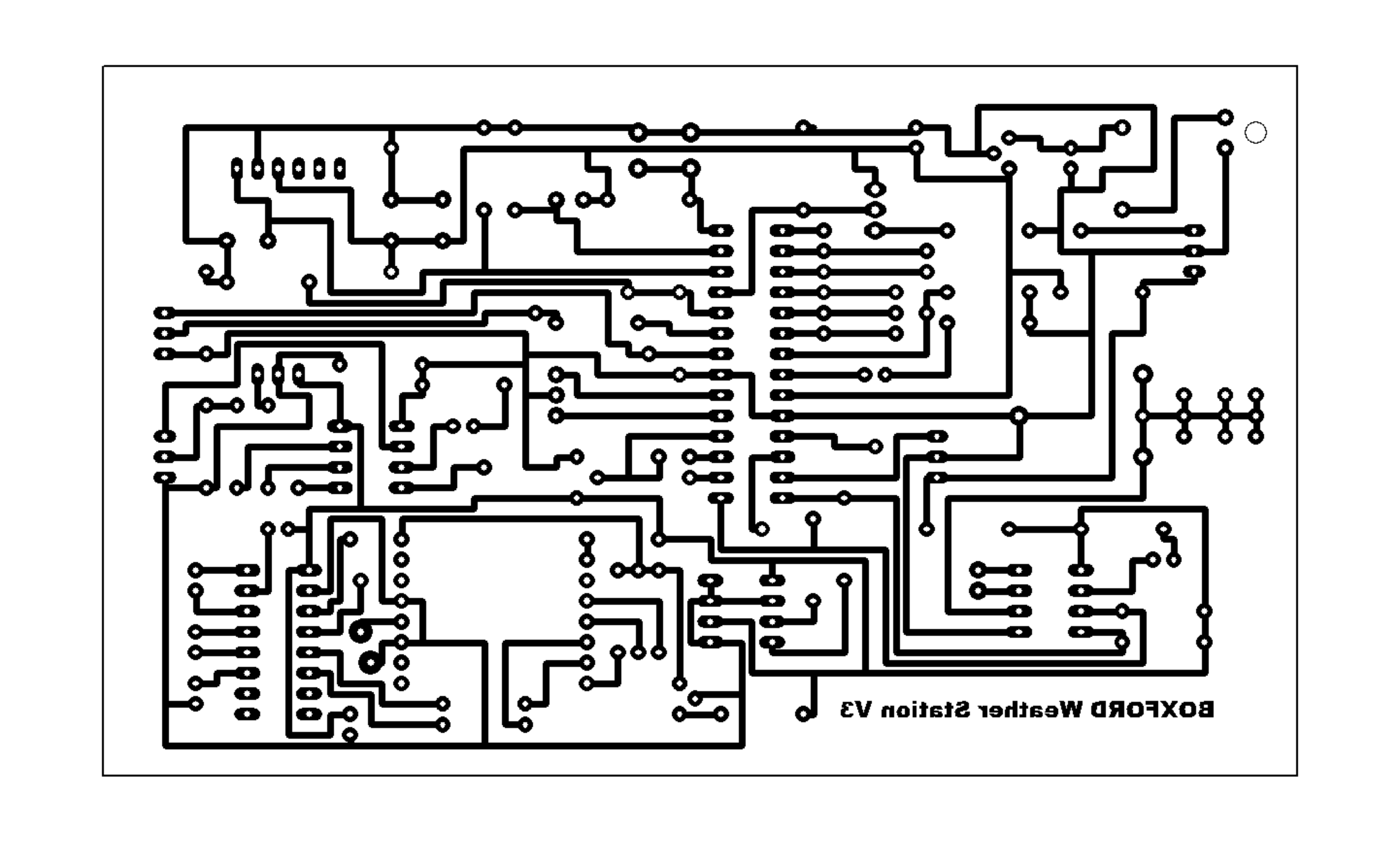
The Circuit Board
Since the version 3 board the manufacturer of the radio chip has added some new facilities that prompted an upgrade. They added two LED to what were empty pins so that you can see the transmission taking place and also see any received information on the other LED. Furthermore they have altered the setting of the baud rate making 4800 baud low low instead of high high. These features are now available on the V5 board. The video was taken whilst assembling a type 3 board so until you get to the radio section the advice holds true.
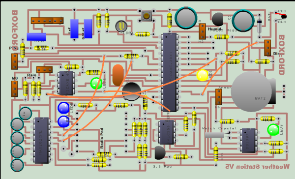
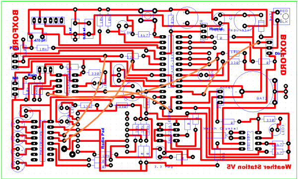
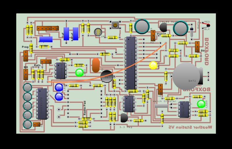
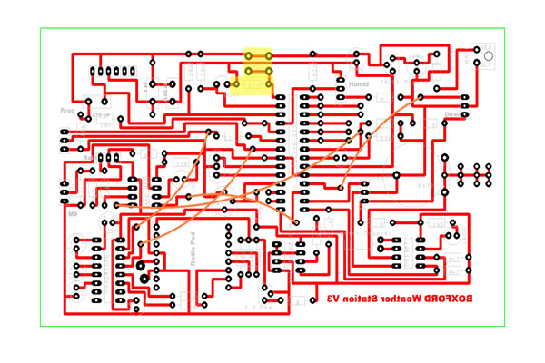
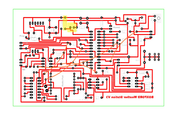
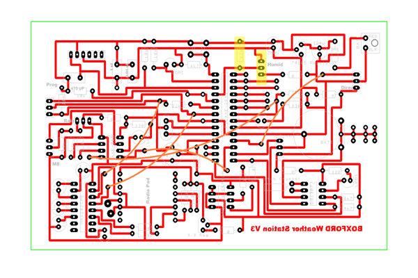
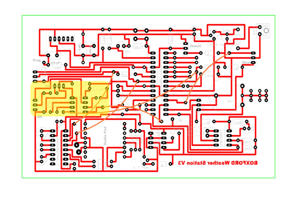
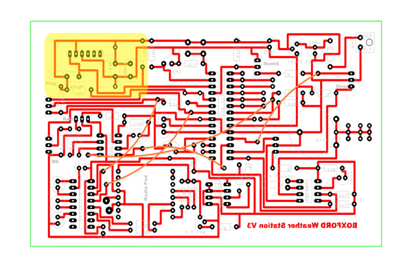
Artwork as a Jpeg - Download Circuitboard in Real PCB Format - Download Since the original board was made I spent some time updating the circuit to reduce the number of cross board wire connections to one.
Artwork as a Png - Download Circuitboard in Real PCB Format - Download
The receiver board has also been finalised and is as follows.
Artwork as a Jpeg - Download Circuitboard in Real PCB Format - Download
|
|||||||||||||||||||
Working through the sensor circuits. The Light Detection Circuit. The detection circuit is a simple resistance bridge unfortunately Yenka will not allow the alteration of the LDR value which should be 10K Ohms not 1 Meg. With a 10K LDR the voltage on the analogue input can swing from 0 (Dark) to 255 (Light) which would then be transmitted back to the PC once per minute.
The Digital Temperature Chip:- The Dallas Semiconductor DS18B20 - 1 Wire Digital Thermometer. Requires no external components. Can be powered from data line. Power supply range is 3.0V to 5.5V. Zero standby power required. Measures temperatures from -55°C to +125°C. Fahrenheit equivalent is -67°F to +257°F ±0.5°C accuracy from -10°C to +85°C. The net result is a very accurate simple to implement device which only needs a resistor to work with a picaxe.
Data Sheet - Download
The Humidity Circuit :- The humidity circuit is based around the Honeywell HIH 4000. The HIH-4000 Series delivers instrumentation-quality RH (Relative Humidity) sensing performance. Direct input to a controller or other device is made possible by this sensor’s near linear voltage output. With a typical current draw of only 200 μA, the HIH-4000 Series is ideally suited for low drain, battery operated systems.
Data Sheet - Download The Air Pressure Circuit :- The MPX4100A/MPXA4100A series piezoresistive transducer is a state–of–the–art, monolithic, signal conditioned, silicon pressure sensor. This sensor combines advanced micro machining techniques, thin film metallization, and bipolar semiconductor processing to provide an accurate, high level analogue output signal that is proportional to applied pressure. Data Sheet - Download The Anemometer Circuit The Anemometer circuit uses the new ratiometric ss490 Hall effect sensors. I bought these sensors only by chance as they were new and looked interesting. It was only at the point that I put one in a breadboard that I realised that they may be fantastically better than normal Hall Effect sensors for micro controllers. Normally to use a hall effect sensor you need a whole Schmidt trigger circuit to make the unit and its signal visible to a micro controller. When you attach 5 volts to the Ratiometric you get 2.5 on the output pin which was intriguing i then ran a magnet past the sensor and it went up to 5v and then back to 2.5 as the magnet passed. So I thought OK that's the range, then I passed the other pole past the sensor and it went to zero volts. It dawned on me that using opposing poles on a disk would make the signal dip through zero to five volts and back in a wave. It then struck me that the simple COUNT command would be able to read these waves despite the raggy nature but because the signal was a full scale deflection. I made a Meccano rig with the sensor below a disk of eight magnets, 4 facing north and 4 facing south and the count command could see the rotation and counted four pulses per rotation. Hence the circuit became :-
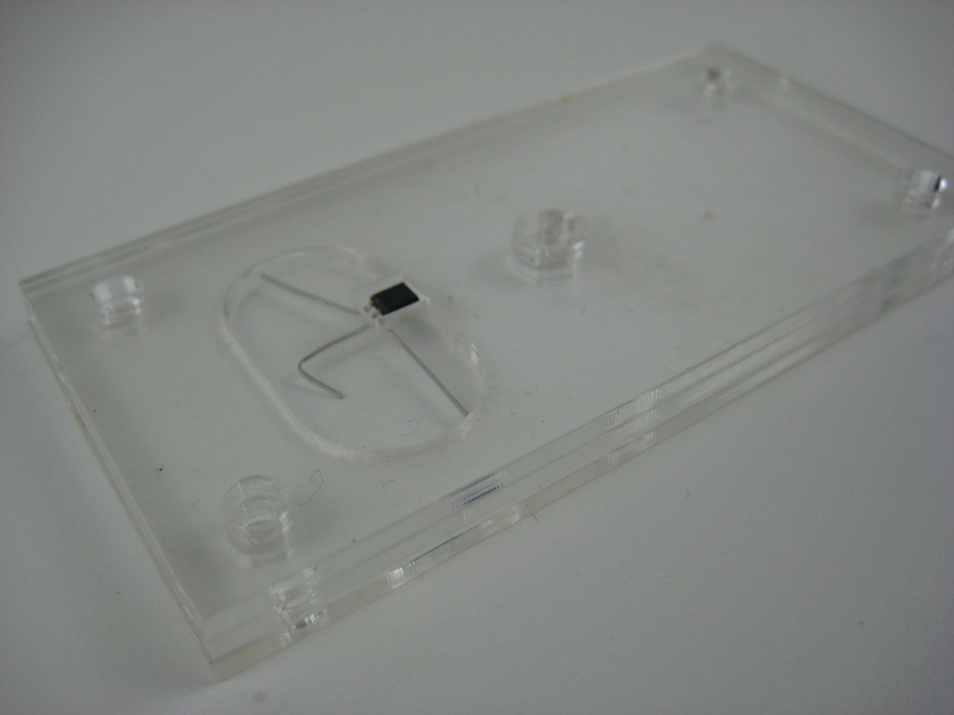
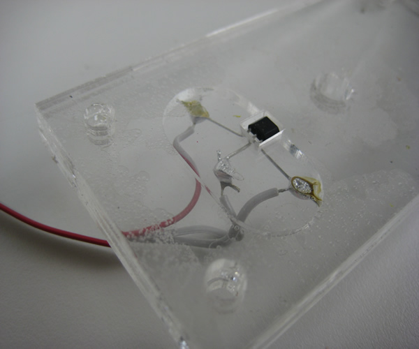
Data Sheet - Download To simplify the installation of the trimetric sensor a locator for the magnets and the sensor in a sandwich this works best cut from 2mm acrylic but you can also use the 3mm acrylic version from the anemometer arm laser cut with a sheet of card packing the sensor up to level with the surface.
2D Draw - Download
This three part shield is intended to position the sensor directly under the magnets on the spinning disk and keep the legs from shorting together. Bend legs on the Trimetric Hall Effect Sensor.
The chamfered face of the sensor faces up. This places the legs in a fixed order the left being +Volts the middle 0Volts and the right the output looking from the top (Chamfered side).
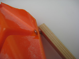
On the wire (in this case ribbon cable) the red is plus the middle 0volts and the right gray is the output from the sensor. This also matches the pinout of the SIL 3 way connector on the circuit board. The Rain Detector :- Again using the ability of the trimetric sensor but this time putting the output voltage into an analogue pin the rain detector uses a seasaw system that measures the rain each time the seasaw flips. It was through that this could happen during transmission of the data and a vital rain measurement lost. Therefore an M8 was assigned the task of monitoring the seesaw. When the hall effect sensor is placed in the side wall it must sit at the end of the slot. None of the wiring or the sensor should stand proud of the plastic surface, otherwise this would interfere with the movement of the seesaw. (Picture) The rain measuring seesaw.
The hole for the axle is drilled exactly 20mm from the top of the seasaw directly in the middle of the flat plane.
Magnet Placing Tool
Magnet held in place while glue sets.
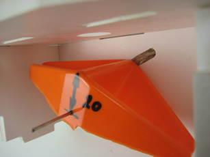
Seesaw placed to ensure it triggers the sensor.
Final Assembled Rain Gauge
When the final assembly is done you may notice some spacing between the walls and the seesaw, it is important to fill this to ensure that the seesaw has no gap between it and the sensor, at the same time there must not be too much packing or washers to create any friction that may cause the seesaw to fail to tip..
The Radio Communication Circuit. The SMARTALPHA Radio Modem module provides a simple interface wireless communications module for the transfer of data at of up to 115kbps. Its unique features of narrow band operation and user channel selection combined with excellent interference rejection make them an ideal choice for next generation applications. The transceivers have the functions of a complete radio modem and simply require CMOS/TTL data at the transmit input and the corresponding transceiver(s) output the same data. Preamble and CRC are automatically generated and added to the RF signal To ensure that the signal quality is maintained a MAX232 chip was added to condition the signal levels. A circuit was selected from the www.sodoityourself.com website. RF Solutions - Test / Setup Software - Download
|
|||||||||||||||||||
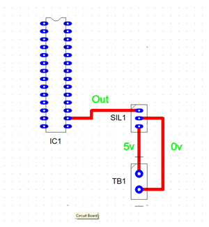
Building The Circuit Board. The First Components. Assembling the circuit board using traditional methods would involve components going in very much in height order however this does not allow the board to be tested at each stage. For this project we will assemble that board section by section and test as we go. The board will be started by putting the chip sockets in then the 5v regulator (make sure that polarity has been checked and that the regulator is producing 5volts. A video also covers each section to help explain the assembly.
Video Of First Few Components.
|
|||||||||||||||||||
Next we will insert the 28pin Picaxe chip, the 22k, the 10k resistor and the connector pins . Picaxe 28 and Program Components
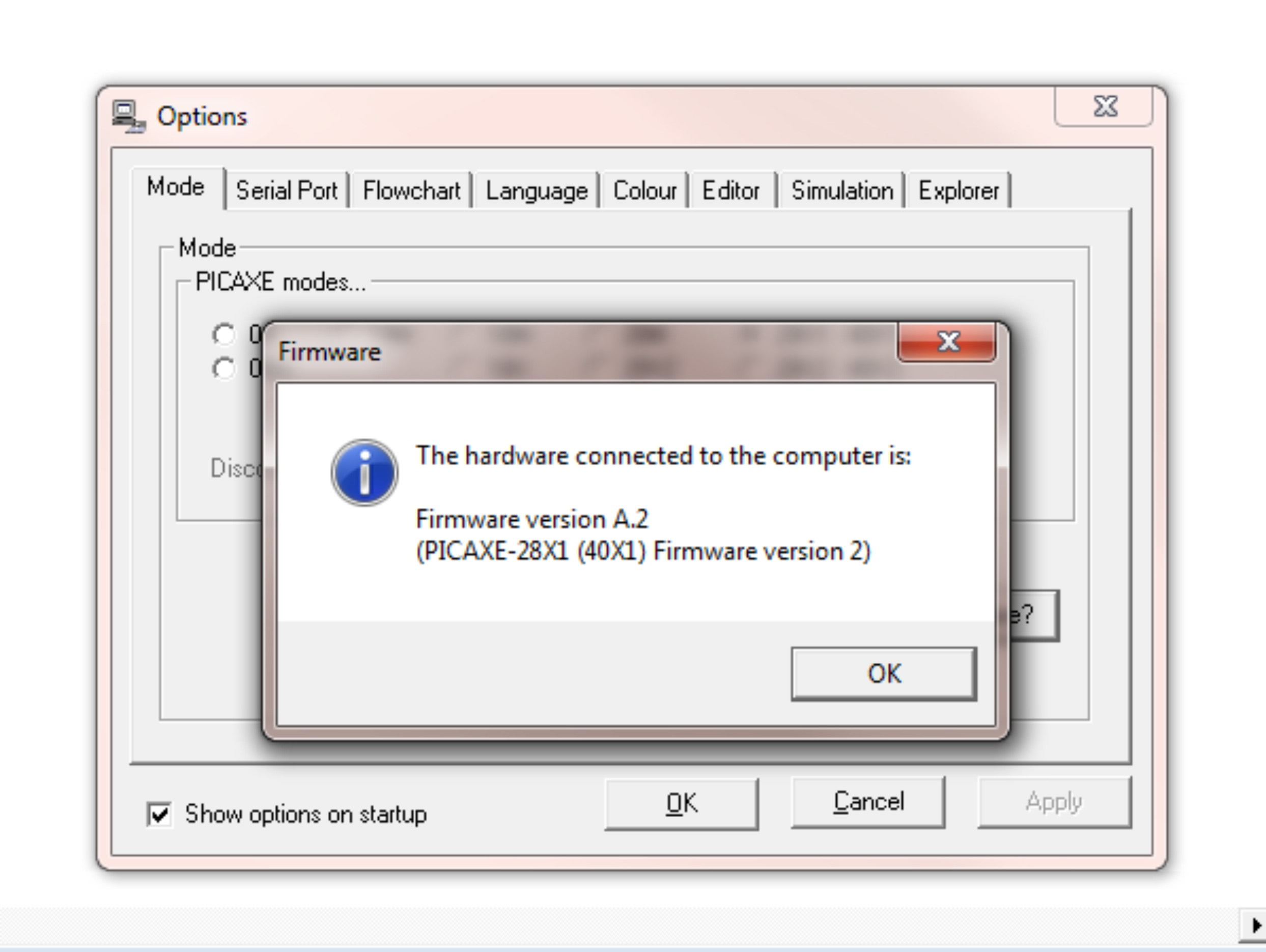
In the Picaxe editor software select View and options then press the firmware button. If the unit is working correctly the software will respond with the firmware version.
At this point I would always relate to the students that the unit has a "Heartbeat" The valuable part is that within a very few components we have proven that the unit is working and that the pupil is soldering properly. Should thier be problems the circuit is very easy to trace because so few components are involved.
|
|||||||||||||||||||
The next stage will be to add an LED and a 330 ohm resistor which is used as a general feedback tool. Once these are added using the programming link the program Test001 will be sent to the picaxe.
Program - Test 1 high 0 pause 3000 main: low 0 pause 300 high 0 pause 300 go to main Program 1 - Download
LED & Reset Button
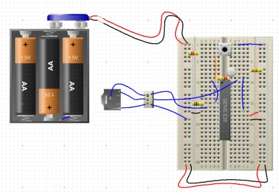
If you wish to make the circuit on a breadboard this is the Heartbeat Circuit.
Download The Circuit Wizard Breadboard - Download With this program loaded the LED should flash. We will then move on to adding the Reset button the same test program will show this works by holding the LED on for three seconds after each reset before resuming flashing.
|
|||||||||||||||||||
The next Subsystem we will install is the Light Dependant Resistor. The LDR is on a flying lead to allow it to poke out of the box and measure the direct light levels. The Program - Test002 high 0 pause 3000 main: low 0 readadc 0,b0 ' b7 = light level ' debug b0 w1=b0*2 pause w1 high 0 pause w1 goto main Program Test002 - Download
LDR
|
|||||||||||||||||||
We now move on to the Digital Thermometer the flat side of the thermometer faces the M8 socket it also faces away from the big 28 pin picaxe. Program Test 03 high 0 pause 3000 main: low 0 ReadTemp 0, b0 ' outside temp Debug w0 goto main Program Test 03 - Download
Temperature Sensor
|
|||||||||||||||||||
The humidity sensor is quite delicate and should be treat as such. It needs to go into the board with the face that looks like a small chip is embedded into it facing away from the 28pin picaxe. The Program - Test002 high 0 pause 3000 main: low 0 ' read humidity readadc 2,b2 debug b2 goto main Program Test004 - Download
Humidity Circuit
|
|||||||||||||||||||
The 1307 clock module has a number of discrete components one of which the resonator must be compatible. Once all the components are fitted the clock can be set with the setting program. Clock setting Program - Test 05
rem set order is - seconds minutes hours DOW(0=mon) dateday datemonth dateyear ??? writei2c 0, ($15, $05, $14, $01, $22, $04, $10, $10) pause 400 clock: low 0 pause 400 readi2c 0, (b0, b1, b2, b3, b4, b5, b6) ‘ read sec, min, hour high 0 debug goto clock end Test Program 005 - Download
Clock Module Fitting
|
|||||||||||||||||||
The M8 chip is used to monitor the rain seesaw that measures rainfall continuously. The Picaxe calls the M8 and asks for the rain value each time it reports to the PC.
M8 Rain Gauge Chip
|
|||||||||||||||||||
The pressure circuit is tested with the main software and should give a reading between 900 and 1100 approximately in the UK.
Pressure Gauge Section
|
|||||||||||||||||||
Fitting Anemometer Connector
|
|||||||||||||||||||
Fitting the memory chip
Memory Chip Installation
|
|||||||||||||||||||
The radio transceiver
Radio Transceiver Test Bed.
|
|||||||||||||||||||
The Radio Receiver
Artwork as a Jpeg - Download Circuitboard in Real PCB Format - Download |
|||||||||||||||||||
The software for the PICAXE 28 - Download The software for the PICAXE M8 - Download
|
|||||||||||||||||||
The Software For The PC
Still under final construction the final version of this software will be launched shortly. Please email if you need it sooner and I will release a Beta version.
|


