|
||||||||||||||||||||||||
The Final Working Automata
Close Up of the Acrobat. The mechanism is actually know as a chaos mechanism. The smooth rotation of the shaft will produce a movement in the legs which is impossible to predict mathematically. Hence the chaos mechanism.
The gears drive the Automata. In the middle of the base is the micro switch which is set to normally closed so that when the switch is closed the circuit is broken. Thus the button bypasses the microswitch starting the motor which them moves the parking block away from the microswitch so that when the button is released the circuit is still made by the microswitch. The motor will then run until the parking block returns to the microswitch location again breaking the circuit and stopping the motor. A certain amount of "fiddling" is necessary to get the microswitch and the block to stop at just the right spot so that the front glass rectangular shape is perpendicular.
|
||||||||||||||||||||||||
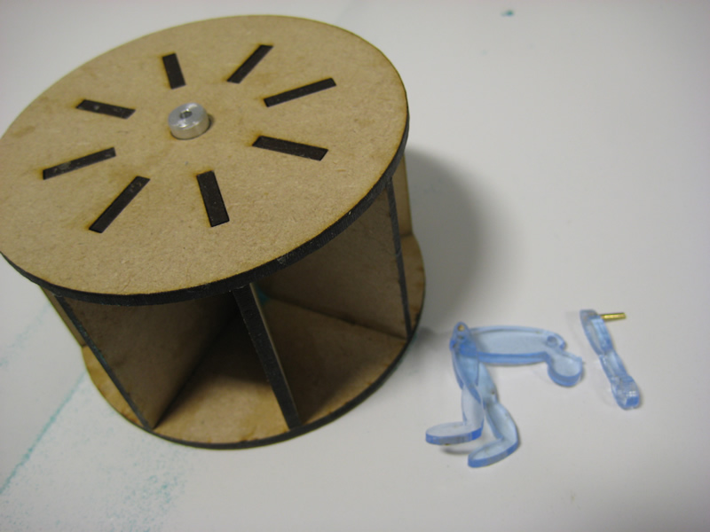
From the rear we can see the actual mechanism. This constitutes a hopper feeding a simple paddle wheel or water wheel, the hopper has an opening on one side only, this accepts sand as the unit rotates, the sand stays at the bottom of the box and flows into the upturned hopper side as it passes the bottom, the whole unit then rights itself the hopper is back at the top now full of sand. The original sand automata were boxes and the user had to turn them over by hand. For education the gear and the motor has been added to bring the project nearer to the requirements of an A. The unit has more than 3 materials it incorporates a number of mechanisms. It has some electronic aspects. The involute profile of the gears add depth to the portfolio.
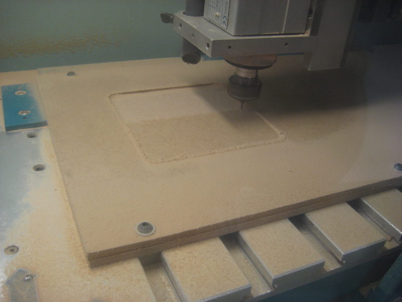
It was decided that this project would be cut from 6mm mdf and instead of opting for the A1 with the vacuum bed (The easy option, the A1 eats sheet materials like no other). It was decided that we would look at bolting the board down on the A3, the bed on the A3 is fully T slotted and it is often forgotten that your sheet and the sacrifice board can have strategic holes drilled into them and the board held down directly on the T Slots. This requires a certain amount of care, if the tool collides with a bolt it will be damaged or may even break. To help stop this happening in the drawing I have made "No Go" areas to try and keep the tool away from the bolts. It is also worth while learning to alter the G&M code as the tool normally runs at the height of 2mm above the table between cutting jobs, thus if the bolts are high then the tool could easily catch the protruding head.
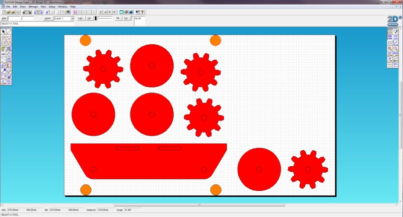
The orange areas mark where the bolts protruded. It is wise to steer clear of these for the reasons stated.
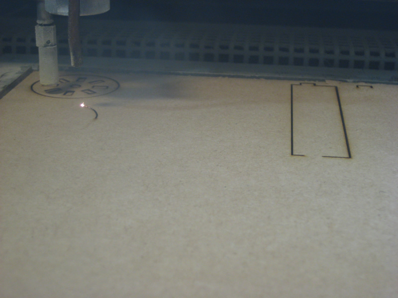
Cutting out the box tops.
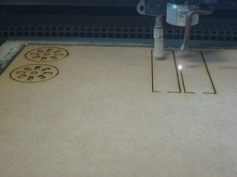
It was chosen to laser cut the wheel out of 3mm MDF, thus adding another process and more depth to a potential portfolio.
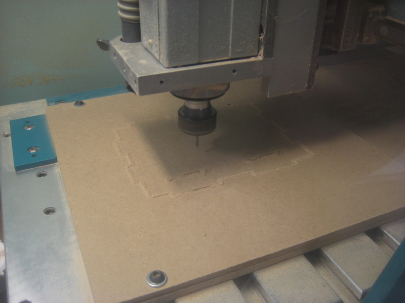
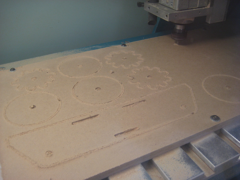
Cutting the Base and small gears, The bolts are the smallest we could find with domed tops. The hole could be spot drilled to make the head sit below the surface.
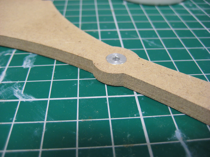
Impressed Aluminium Bush.
The diameter of the wheel is important and the larger the diameter of the wheel the more leverage is developed. However this then also becomes a factor of the individual bucket or segment size as a small bucket will only hold a correspondingly lighter charge of sand.
Finally having experimented with all sizes of gap it was decided that the same could be achieve with two drilled holes which means it is easy to control the flow. Differing granular sizes of sand and grit shape will make for differing flow rates again an aspect that can be researched for the portfolio. The sand in this automata is art sand bought on ebay it is intended for use as a make your own coloured sand bottle toy. I made two 6mm holes and this seemed to be the best payoff between time versus speed of acrobat.
|
||||||||||||||||||||||||
| Sand Automata Files in ZIP Format - Download | ||||||||||||||||||||||||
| Sand Automata Files in RAR Format - Download |